


Pneumatic Conveying Dust Explosion Risks: NFPA Requirements and Prevention
|
Date:
|
|
Reading Time: 10 minutos
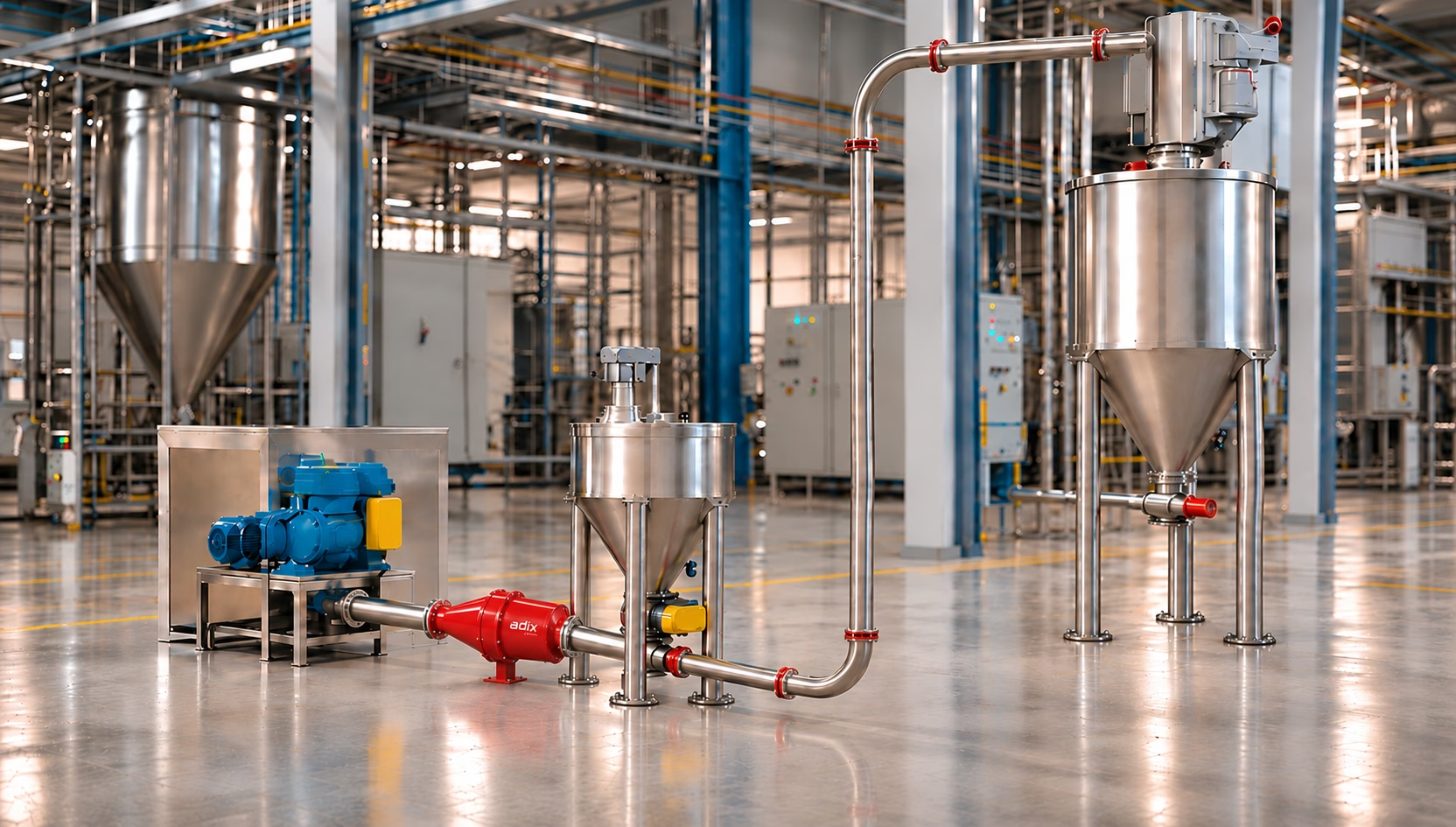
Can a Roots blower cause a dust explosion? In positive-pressure dilute-phase pneumatic conveying, the answer is yes — even when the blower itself never touches combustible dust.
The Hidden Hazard in Pneumatic Conveying
Pneumatic conveying systems are widely used in food processing, grain handling, chemical manufacturing, pharmaceutical production, and other industries handling combustible powders. Positive-pressure dilute-phase conveying provides continuous transfer between processing equipment, storage silos, and separation systems. When combustible dust is involved, however, an ignition source does not necessarily originate where the eventual explosion occurs.
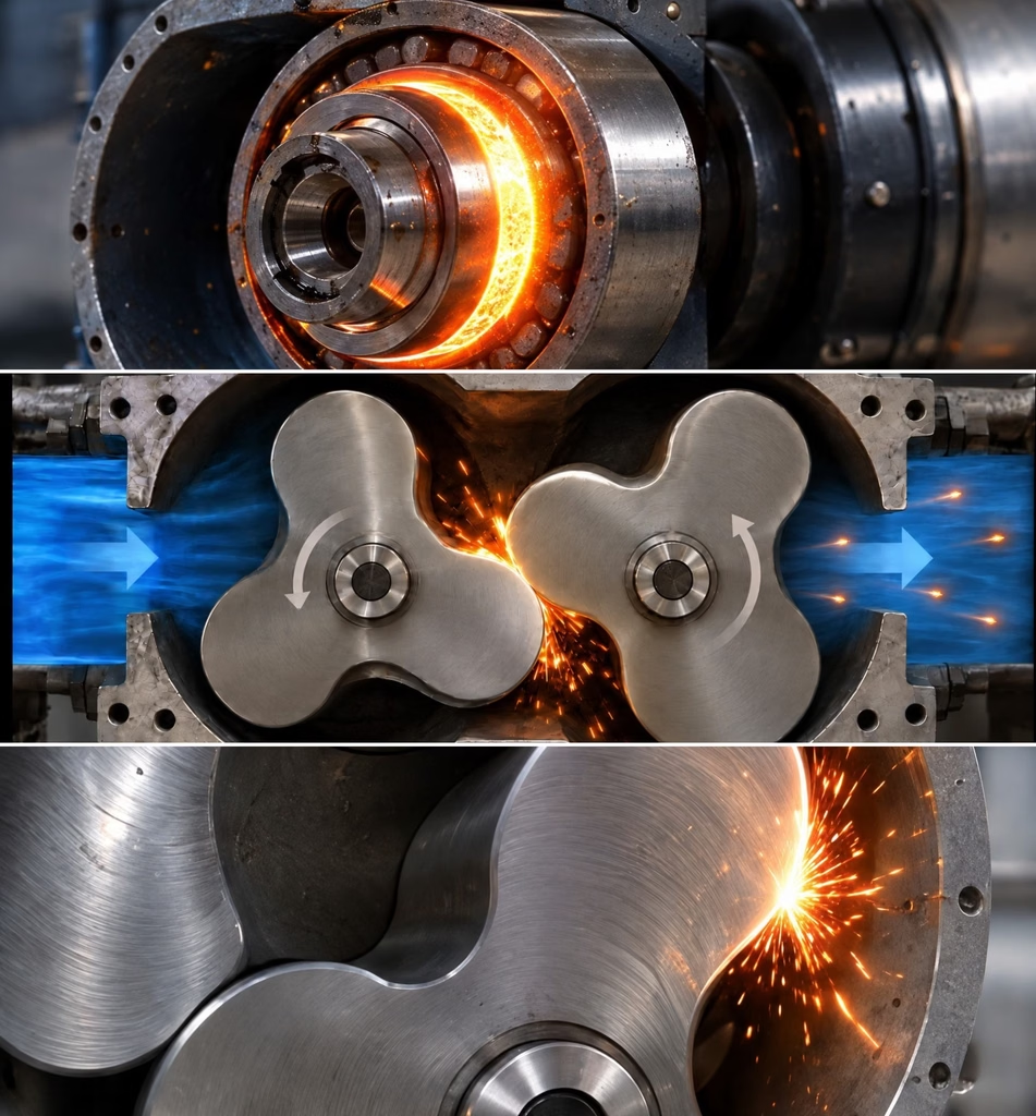
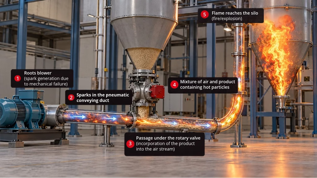
A Roots-type positive displacement blower can generate mechanical sparks or hot particles during abnormal operation, even when it handles only clean air. Such ignition sources may travel downstream before encountering combustible powder. The blower may contain no combustible dust, yet still become the origin of an ignition source capable of triggering an explosion elsewhere in the system. [1]
How Positive-Pressure Dilute-Phase Conveying Works
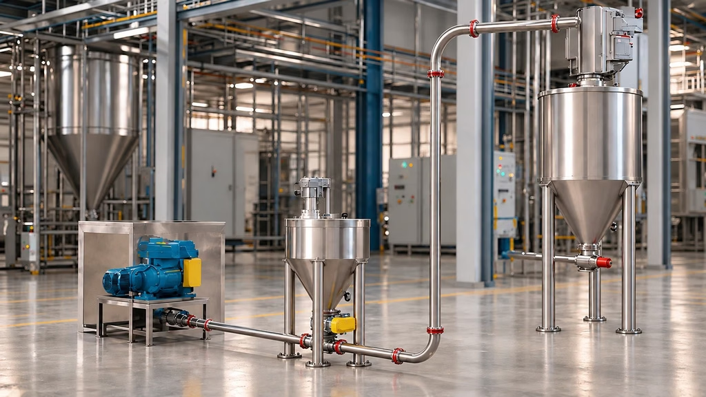
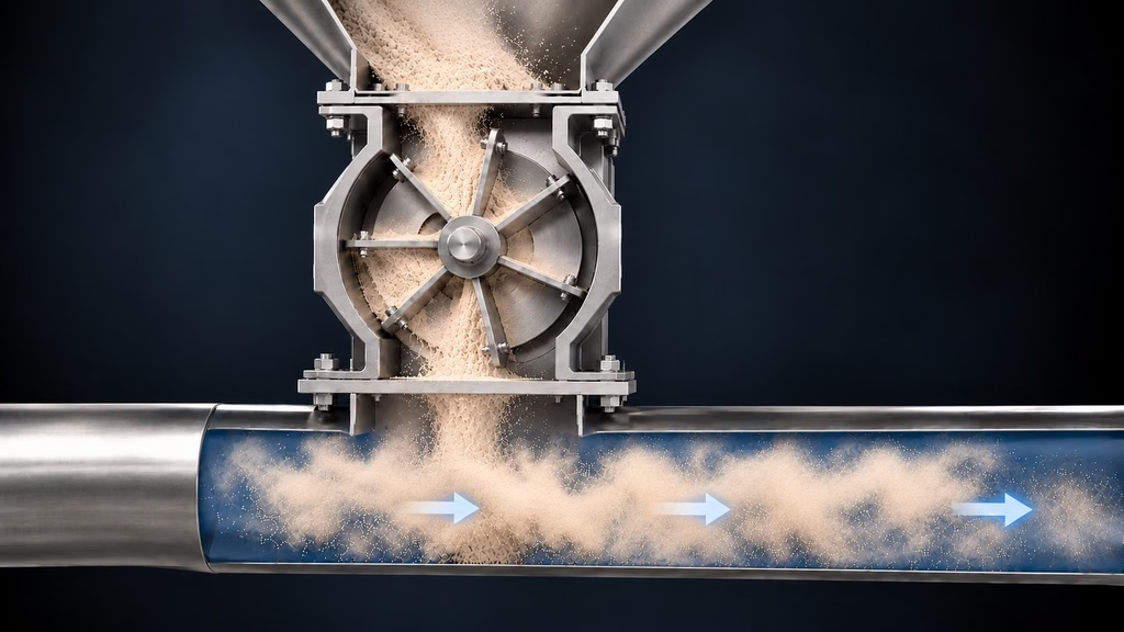
A typical system comprises a Roots blower, a clean-air pipeline, a rotary airlock or material feeding device, a dust-laden conveying line, and a receiving silo, cyclone, baghouse, or other separator. Powder enters the airflow downstream of the blower. The clean-air section may therefore transport ignition sources even though an explosive dust atmosphere is not normally present there.
Where Can Explosible Dust Atmospheres Form?
A dust deflagration requires combustible dust dispersed at an explosible concentration, sufficient oxidant, and an effective ignition source. Confinement contributes to pressure buildup. Concentrations around 1 kg/m³ can occur in dilute-phase conveying, but actual values vary with solids loading and operating conditions; explosibility must be evaluated against the material’s minimum explosible concentration (MEC). [1]
European operations: Directive 1999/92/EC, Article 4 and Annex I, requires assessment of the likelihood and persistence of explosive atmospheres and provides the framework for hazardous-area classification. EN 1127-1:2019 addresses explosion hazard identification, ignition-source assessment, prevention, and protection. [10, 11]
Conveying pipelines
Powder suspended in the airflow may form an explosible mixture when concentration and other conditions are favorable. The pipeline can also transmit flame and pressure between connected equipment. A nominal solids loading alone does not prove the mixture exceeds the MEC.
Receiving silos and storage vessels
Pneumatic filling can generate localized dust clouds near the inlet and within the receiving vessel. Hot particles carried from upstream equipment may reach these locations during filling.
Baghouse dust collectors
Dust-laden chambers and filter cleaning cycles can disperse combustible dust. A deflagration within a baghouse can cause significant internal pressure and may transmit flame to connected equipment.
Cyclones and receiving hoppers
Material separation and discharge may create dust clouds. Their interconnections must be evaluated for potential propagation and appropriate isolation. [1, 2]
Ignition Sources in Pneumatic Conveying Systems
Mechanical sparks generated by Roots blowers
Roots blowers have closely spaced rotating lobes designed to run without contact. Mechanical failures can produce friction, impact, incandescent particles, or hot fragments. Credible failure mechanisms include rotor-to-rotor contact, rotor-to-casing contact, loss of clearance, bearing failure, timing-gear or lubrication problems, and foreign metallic objects entering the air inlet. Whether a particle can ignite a particular dust depends on its mass, material, temperature, oxidation behavior, and the dust’s ignition sensitivity. [1, 3, 4]
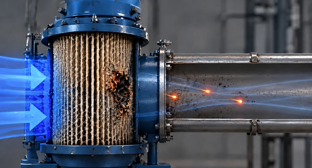
External sparks and inlet-filter fires
External sparks or burning debris may be drawn toward the blower inlet. Depending on filter construction and the incident, ignition of inlet-filter media may generate burning material capable of reaching the airflow. This scenario requires an assessment of inlet location, external hot-work exposure, filtration, and the credible path into the conveying line.
Hot surfaces and overheated bearings
Bearings and rotating components can overheat because of lubrication loss, wear, or misalignment. In a clean-air blower, a hot bearing does not automatically contact dust, but its failure may produce internal friction and hot particles. Temperature and vibration monitoring are valuable preventive controls.
Electrostatic discharges
Contact and separation between powder, pipes, filters, and hoses can generate electrostatic charge. Grounding, bonding, conductive components, and selection of suitable flexible connections should follow the process hazard assessment and NFPA 77 guidance. [5]
Electrical and other ignition sources
Motors, sensors, switches, and instruments should be suitable for the applicable hazardous location classification. Foreign metallic objects, rotary-valve friction, smoldering material, and maintenance activities must also be considered. [6]
The Traveling Spark: Ignition Far Downstream
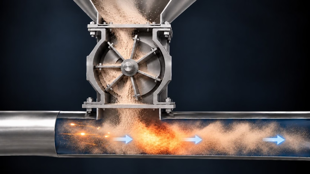
Imagine a bearing fault that leads to rotor misalignment and metallic contact inside a blower. A hot particle enters the clean-air stream, travels downstream, and reaches the rotary airlock where combustible powder is introduced. If the particle retains sufficient ignition capability and encounters an explosible dust cloud, a deflagration may start in the line or receiving equipment. The ignition-source origin and the explosion location can be separated by a substantial distance.
Explosion Consequences and Propagation
Pressure development
Dust deflagrations can generate rapid pressure rise. Pmax characterizes maximum explosion pressure under specified test conditions, while Kst characterizes the normalized maximum rate of pressure rise. These are severity parameters, not measures of ignition probability.
Flame propagation through pipelines
Connected pipelines can transmit flame and pressure from an initiating vessel to another piece of equipment. Turbulence and precompression can intensify combustion, so isolation needs to be considered alongside vessel protection. [2, 7]
Secondary explosions and consequences
An initial event can disperse accumulated dust and create conditions for secondary explosions. Consequences include personnel injury, vessel rupture, damage to adjacent systems, prolonged downtime, and major business interruption.
Evaluating Risk Under NFPA 660
A Dust Hazard Analysis (DHA) should cover the complete system: blower, clean-air section, feed device, dust-laden line, receiver, and interconnections. It should consider normal operation, foreseeable faults, startup, shutdown, maintenance, and credible ignition-source transmission. NFPA 660 provides the primary combustible dust framework; NFPA 68 and NFPA 69 support selection of applicable venting, prevention, and isolation systems. [1, 2, 7]
For EU workplaces, Directive 1999/92/EC, Article 3 establishes a hierarchy: prevent explosive atmospheres, avoid ignition where atmospheres cannot be prevented, and mitigate explosion effects. Article 4 requires an overall assessment that includes interactions and connected spaces; Article 8 addresses the explosion protection document. EN 1127-1:2019 complements this approach with a systematic explosion risk assessment methodology. [10, 11]
| Parameter | Relevance |
|---|---|
| Kst | Explosion severity and protection design |
| Pmax | Maximum pressure and protection design |
| MEC | Minimum explosible dust concentration |
| MIE | Electrical spark ignition sensitivity |
| MIT cloud / laver | Hot-environment and dust-layer ignition sensitivity |
| LOC | Oxygen limitation and inerting assessment |
| Particle size / moisture | Influence on dispersion and explosibility |
MIE testing does not by itself establish the ignition capability of a hot metallic particle; different ignition mechanisms transfer energy differently.
Explosion Prevention: Interrupt the Ignition Chain
Mechanical integrity and monitoring
Maintain rotor clearances, bearing condition, lubrication, alignment, inlet filters, and timing gears. Monitor vibration, temperature, and abnormal pressure conditions; provide alarms and shutdown interlocks where justified. Maintenance reduces risk but cannot guarantee that mechanical failures will never occur.
SparkCatch: Passive inline ignition-source mitigation
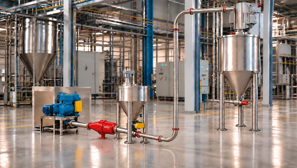
ADIX SparkCatch is intended to reduce the transmission of certain ignition-capable hot particles in conveying air. In this configuration, its strategic installation location is between the Roots blower and the rotary airlock or other powder injection point — while the line still contains clean air.
Its internal geometry modifies entrained particle trajectories and increases their effective path or residence time, promoting thermal energy dissipation. Within the device’s validated operating envelope, this can reduce the ignition capability of hot particles before they reach combustible powder. The passive principle does not require electrical power for its basic operation.
SparkCatch should be described as an additional prevention layer rather than a substitute for required venting, suppression, or explosion isolation. Performance against mechanical sparks, incandescent particles, or established flames must be supported separately by relevant test evidence and installation conditions. [1, 3, 4]
Spark detection and extinguishing
Active systems detect radiation from sparks or glowing particles and initiate extinguishing downstream. Performance depends on conveying speed, detector coverage, response time, available distance, extinguishing medium, and maintenance. These systems may complement passive mitigation.
Static electricity and equipment suitability
Bond and ground conductive components, evaluate hoses and insulating materials, and select electrical equipment for the applicable classified location. Assess non-electrical equipment for friction, impact, hot surfaces, and electrostatic charging. [3–6]
Other preventive controls
Depending on the DHA, additional measures can include inlet filtration, foreign-body removal, process interlocks, and inerting where feasible.
Explosion Protection: Limit Consequences if Prevention Fails
Explosion venting and flameless venting
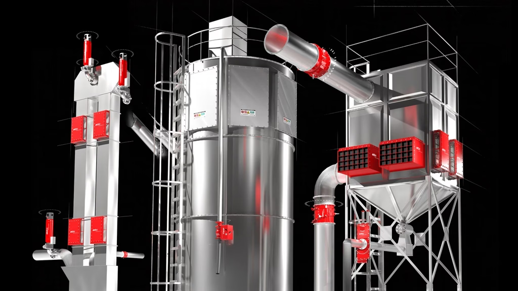
Explosion venting provides controlled pressure relief to reduce the pressure developed in protected equipment. Flameless venting can reduce external flame and thermal effects where conventional outdoor venting is impractical. Both require suitable design for the equipment, dust properties, and installation conditions. [7]
Explosion suppression
Suppression systems detect an incipient deflagration and rapidly discharge suppressant to limit combustion and pressure development. Suitability must be validated for the protected equipment and process conditions. [2]
Explosion isolation
Suitable isolation technologies can include certified or otherwise appropriately validated passive flap valves, fast-acting mechanical valves, chemical isolation, and rotary valves designed for explosion isolation. An ordinary rotary airlock or flap valve should not automatically be considered an explosion isolation device. [2]
Why Prevention and Protection Work Together
An effective strategy uses complementary layers. Blower maintenance and monitoring reduce the likelihood of abnormal conditions; SparkCatch may reduce transmission of certain hot particles before powder injection; spark detection and extinguishing can address applicable ignition-source pathways; and venting, suppression, and isolation reduce consequences if a deflagration occurs. Each measure addresses a different part of the risk.
Conclusion: Prevention Starts Before the Powder Enters
In positive-pressure dilute-phase pneumatic conveying, ignition sources can originate in equipment that normally handles only clean air. A Roots blower fault may introduce hot particles into the air stream; those particles may travel downstream and reach combustible dust clouds in conveying lines, silos, cyclones, or baghouses. The DHA should follow credible ignition sources from their origin through their potential transmission and ignition location.
Properly selected and validated inline SparkCatch mitigation can add a preventive layer between the blower and material introduction point. Where required, explosion venting, suppression, and isolation remain essential. The strongest approach is to prevent ignition where possible while limiting the consequences if prevention fails.
ADIX designs and manufactures explosion prevention and protection solutions for combustible dust handling processes. Contact our engineering team to review your pneumatic conveying application.
References
[1] NFPA 660 (2025), Standard for Combustible Dusts and Particulate Solids — DHA, ignition hazards and process-specific requirements.
[2] NFPA 69, Standard on Explosion Prevention Systems — applicable prevention, suppression and isolation provisions.
[3] ISO 80079-36:2016 — Non-electrical equipment for explosive atmospheres: basic method and requirements.
[4] ISO 80079-37:2016 — Non-electrical equipment protection by constructional safety, control of ignition sources and liquid immersion.
[5] NFPA 77, Recommended Practice on Static Electricity.
[6] NFPA 70, National Electrical Code — applicable hazardous location articles.
[7] NFPA 68, Standard on Explosion Protection by Deflagration Venting.
[8] VDI 2263 series — Dust fires and dust explosions; hazard assessment and safety measures.
[9] FM Global Property Loss Prevention Data Sheet 7-76 — Combustible Dusts.
[10] ATEX Directives 1999/92/EC and 2014/34/EU — European workplace and equipment frameworks. Additional citation: Directive 1999/92/EC, Articles 3, 4 and 8; Annex I (hazardous-area classification) and Annex II (minimum workplace requirements).
[11] EN 1127-1:2019 — Explosive atmospheres: explosion prevention and protection; basic concepts and methodology.
[12] EN 13463 series (withdrawn / superseded) — Historical ATEX standards for non-electrical equipment. EN 13463-1 was replaced by EN ISO 80079-36:2016; relevant protection concepts previously in EN 13463 were replaced by EN ISO 80079-37:2016. Use EN ISO 80079-36/-37 for current equipment assessment.
